Table des Matičres
Search
Website Design and Content © by Eric Krause,
Krause House Info-Research Solutions (© 1996)
All Images © Parks Canada Except
Where Noted Otherwise
Report/Rapport © Parks Canada / Parcs Canada
---
Report Assembly/Rapport de l'assemblée © Krause
House
Info-Research Solutions
Researching the
Fortress of Louisbourg National Historic Site of Canada
Recherche sur la Forteresse-de-Louisbourg Lieu historique national du Canada
PRINCESS
BASTION REPORT:
A SURVEY OF THE AREA FROM THE RIGHT REENTRANT
ANGLE OF THE PRINCESS BASTION TO THE RIGHT REENTRANT
ANGLE OF THE BROUILLAN BASTION, AND THE RELATION OF THIS
AREA TO CAP NOIR
BY
MARGARET FORTIER
February, 1966
(Supervision: W. Stevenson, J. Hanna)
(Fortress of Louisbourg Report H B 3)
Presently,
only some illustrations are
included here.
For all of them, please consult the original report in the archives of the Fortress of Louisbourg
![]() Return/retour
- Table of Contents/
Return/retour
- Table of Contents/
Table des Matičres
SECTION II
CHAPTER 6
Outer Works
Because of the complex nature of the Princess Bastion itself, the outer works have been considered only in a cursory fashion in so far as they relate to the Bastion's completion and the alterations made in the 1750's. Many fine points which are not essential for a knowledge of the Bastion have, therefore, been omitted. For the present only the area immediately before the Princess Bastion will receive consideration. Such things as the demi-lune which was constructed in the 1750's are discussed because they are essential for an understanding of the Princess Bastion.
CONSTRUCTION OF THE OUTER DEFENSES
I - BATARDEAU
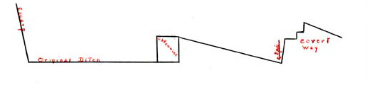
The batardeau was a low wall of cut stone which closed the end of the ditch at the salient angle of the Princess Bastion. Represented on a plan for the first time in 1735 in what looked to be its initial stage, [245] (Figure 7) this wall was not completed until 1738. [246]
An outside view of the Princess Bastion shows the batardeau to be a good deal lower than the right face. its summit appears to have been triangular in shape, a measure taken on such works to prevent the enemy from walking to the fort from the outer works. A drain passes through the batardeau allowing water and waste to pass from a drainage canal in the ditdh. [247] (Figure 9) Indication of the drain can be found on many subsequent plans. [248] (Figures 8, 12 and 22)
Hints as to the width of the beach on the east side of the Fortress are scarce. One reference - made by Knowles and Bastide - allowed that there was room enough for 30 men, presumably side by side, between the batardeau and the sea. They did not specify high or low tide. [249]
II - DITCH
Though it was reported in 1733 that work on the excavation of the ditch had only reached the Princess-Queen's Curtain, [250] a plan of the same year, shows digging before the right face of the Princess Bastion. [251] (Figure 3) Earth from these diggings was slated to be used to form the ramparts, [252] the terreplein and the parapets of the fortifications. [253] For this reason, work on the ditch was continued apace.
It was announced in 1736 that the ditch had almost reached its full size. However, by the end of the next year, it had yet to be completed. Hope was expressed that the job would be finished in 1738. [254] The nearly completed state of the ditch can be seen on a 1737 plan. [255] (Figure 8) A second plan from that year, which undoubtedly mingles the accomplished work with future projections, shows what looks to be a drainage canal running west to east through the ditch. [256] This feature is one not reflected on any plans prior to 1748, but is one which might be taken as fact since drainage through the batardeau out to the-sea is depicted on most plans. (Plate 2)
By 1738 all that remained was to clear the rubble from the ditch, and it seemed that this could be accomplished by the next spring. [257] No further work was reported as having been carried out at this end of the ditch. Had the plans for enlarging the Bastion been carried out by the English, the ditch, the covert way and the glacis would have been extended to a point closer to the sea. [258] (Figure 15)
III - COVERT WAY
The first mention of the covert came in November, 1736. At that time it was said that the walls of the contrescarp would be 2 pieds thick and 8 pieds high, and that, after the parapets of the Princess-Queen's Curtain were completed, the earth from the ditch would be used to form the Terreplein of the covert way. [259]
In June of the next year, it was stated that the French were anxious to perfect the ditches in order to begin work on the masonry of the contresearp. [260] They planned to lay the foundations and begin to raise the contrescarp from the salient angle of the King's Bastion to the Princess Bastion during 1738. Also, since the covert way had been given rough shape during 1737 from the salient angle of the Queen's Bastion to that of the Princess Bastion, [261] they hoped to establish the revetment of the covert way's parapet that same year. [262] It was estimated that if the laborers continued to work through October 1738, the various tasks would be completed. [263]
The dirt from the ditch, which was to be used to form the contrescarp and the parapets, was found to be insufficient for their needs. It was necessary to supplement it with earth from the knolls in the surrounding area whose presence, it was felt, endangered the city. [264]
The goal of finishing and reveting the contrescarp by the end of 1738 was accomplished. [265] The stairs from the covert way to the ditch were all in place that same year. It was thought that the parapets of the covert way would be finished by 1739. [296] There is no record of when they actually were completed.
IV - GLACIS
Work was begun on the glacis in 1737. It was given its rough shape that year with earth from the ditch and surrounding knolls. [267] The wall which supported the glacis along the covert way - the revetment of the covert way - was raised on all sides in 1738. [268] And, by the end of 1740 the work on the glacis was completed. [269]
A 1737 view of the Princess Bastion shows a wall running along the end of the glacis. It proceeds on the same slope as the glacis itself. [270] (Figure 9) This wall is also represented on most plans which detail the outer works to any degree.
ALTERATIONS OF THE 1750'S
The discussion of the outer works in the area of the Princess Bastion
during the 1750's will take two directions for the purposes of this
report. As subjects of the various proposals for strengthening,
the
fortifications at Louisbourg, they are dealt with in a subsequent
chapter. However, as integral parts of the network of fortifications that
were actually being altered and repaired, they will be dealt with here.
Precisely how the changes
made at the outer works fitted in with the several projects put forth
in the 1750's is not, therefore, of immediate concern. Rather, only
specific alterations will be dealt with. The parts of the outer works will
be treated as independent entities; a fiction valid only for the purpose
of simply recording change.
When the French regained Louisbourg, they said almost nothing about the condition of the outer works in the area of the Princess Bastion. In 1749 they reported that the batardeau was in the same state it had been before the siege with the cut stone joints partially defaced. [271] And, two years later the covert way was described as being totally submerged by Cap Noir and caved in due to the poor foundation on which it had been set. Both covert way and glacis required repairs in order to remedy this situation. [272]
All of the projects outlined by Franquet, as far as the Princess Bastion was concerned, were geared toward lessening the danger presented by Cap Noir. Regardless of the degree of their complexity, all the projects included provision for an enlarged covert way and glacis. Some of the proposals were relatively simple, as will be seen. Others, however, involved the construction of a demi-lune and contregard before the Princess-Queen's Curtain and the right face of the Princess Bastion. It was a variation of this project which was finally settled upon by the French.
I - BATARDEAU
As was said previously, the retired battery had come to assume a role of major importance by 1751. Regarding it as one of the most critical points in the Fortress, the French sought to protect it by building a new wall - a "profile" facing the sea from the retired battery to the 2 enlarged covert way. This wall would replace the old batardeau [273] which would be removed in proportion to the advancement of the work on the new wall. [274]
In 1755 it was reported that the foundation of the new seaward wall had been laid and raised 5 pieds. It was planned that work would continue immediately upon the return of good weather, especially since the lime, sand and quarry stone needed for the task were available at the site of the work.[275] During the following year, it was said that the original foundation had been raised only 4 1/2 pieds. [276] And, a third reference stated that during 1755 the seaward wall had been raised to a height of 5 1/2 pieds. [277]
The total height of the wall is not entirely certain, but it would seem to have been a pieds. Four references made after the completion of the wall gave 8 pieds as its height. [278] Only one reference recorded another figure, and this statement was made before the wall was raised above its foundation. This last reference stated that there would be 8 1/2 pieds added to the 4 1/2 pieds laid in 1755, giving, a total height of 13 pieds above the offset. [279]
According to this last document, the wall was to be 6 pieds thick. [280] This figure was supported by one of the later documents, [281] but two others recorded the thickness as 8 pieds and 9 pieds respectively. [282] Since all the references were made by Franquet, it is not possible to give credence to any one of the dimensions on the weight of the author.
The new wall was constructed of dry stones [283] and, apparently, was covered with wooden frames and planking in much the same manner as the Crenelated Wall. [284] Franquet spoke of the planks that would be applied to the beam bearings which were destined to hold a "chemise" [285] of wood as a revetment. This, he felt, would hold the dry stones more easily. [286]
Since the purpose of the wall was to aid in protecting the retired battery from fire from Cap Noir, it would be only logical to expect that the "profile" itself would not be vulnerable to such fire. Built so as to join with the exten6ions of the right face, contregard and covert way, [287] the wall was not exposed to the hill. [288] It was able to be protected on its whole length by musket fire sufficient to hinder troops running along the shore toward the Crenelated Wall. [289]
Because of the incursions of the sea, it had been necessary to place the wall 12 pieds farther back than had been estimated. (Most likely the planned point of contact between the wall and the battery had been at the latter's left angle.) [290] As a result, the wall was not able to aid in protecting the right face and flank of the Brouillan Bastion. Nevertheless, it was felt that in case of an attack on these two parts, there would be a cannon established on the rampart of the left face which would provide cover for them. [291]
How the men and their guns would be situated on the new wall is not known. There is no record of there having been a firing step along its length. There are statements to the effect that there was no parapet on the wall. [292]
At the junction of the new seaward wall with the face of the contregard and with the right face of the Bastion, posterns 4 pieds wide were formed to allow communication between the interior of the fort and the outside. [293] These posterns were backed by "tambours" [294 ]in the form of traverses. Near the one at the contregard, and possibly near the other also, a store for munitions was to be constructed for the defense of the covert way. [295]
The two posterns are not depicted on any plans. However, a plan from 1757 [296] and one from 1758 [297] do show two blocks of some kind sitting near the extensions of the face and contregard which may represent the "tambours" behind the posterns. The plan from 1758 had a similar block shown north of the extension of the face, but there is no record of a postern having been opened at that point. [298] A postern was formed near the covert way to allow passage to a caponier attached to the latter. This is shown on the 1757 plan and indicated on the one from 1758 by a fourth block. [299] (Figures 31 and 32) The munitions depôt does not appear on any plan.
Nothing was said of it, but it would appear from the plans of Franquet's projects that it had been his intention to place a drain in the seaward wall to facilitate the emptying of excess waste from the ditch. It seems that it was to be placed in approximately the same general area as the previous one. [300] (Plates 9, 10, 11 and 12) However, it is not known whether a drain was actually opened in the new wall. Nothing to indicate its presence appears on the plans intended to represent the works as they were.
In 1758 the English reported that the profile had been intended to "compleat the Breach in the S.E. Face [the retired battery] of the Princess Bastion," but it served only as "a sort of Cover'd way to that part". Never finished, it was beginning to give way. The recommendation was made that the wall should be coped in sod to prevent the rain from doing any further damage. [301]
II - DITCH
The removal of the old batardeau and the construction of the new seaward wall meant the automatic lengthening of the ditch by approximately 60-70 pieds. This estimate is based on the knowledge that the new wall extended from the retired battery which was 66 pieds long. The statements given above that the wall had to be brought back 12 pieds probably refer to its having been placed 12 pieds from the end of the battery, reducing the length of the latter to 54 pieds. Allowing for broadening in the area of the ditch, the added length of the ditch probably fell somewhere between 60 and 70 pieds. Several plans indicate that the new wall did not meet the retired battery at its left extremity. [302] (Figures 31, 32 and 34)
The width of the ditch at the salient angle of the Princess Bastion was given as 11 toises 3 pieds in 1751. [303] A profile from the same year recorded the width at a point near the middle of the right face as 12 toises 3 pieds 9 pouces. [304] The depth of the ditch was stated to be 7 to 8 pieds reduit. [305]
The construction of the demi-lune and contregard meant that the character of the ditch would be completely changed. Both these structures would have ditches dug between them and the covert way. Work on this was begun in 1755. [306] It was hoped that the digging from the new ditches would provide materials for use in repairing the fortifications. However, it was found that the digging produced more rocks than earth, and, consequently the works were obliged to draw from the area around Cap Noir. [307]
In order to insure as wide a ditch as possible around the demi-lune, the French sought to maintain a rather steep exterior slope. [308] The final width of the ditch between the demi-lune and the covert way is not known. However, a profile taken in 1756 through the right face, the contregard and the covert way shows the ditch between the face of the Bastion and the contregard to be 12 toises 4 pieds. The ditch of the contregard was shown with a width of approximately 8 toises 2 pieds. (A width of 7 toises 2 pieds was given, but it was measured from the escarp of the projected contregard. The existing structure stopped about 6 pieds behind this escarp.) [309]
By 1756 the ditches were entirely excavated and nearly cleared of the rocks which had been left there for use in building masonry revetments for the demi-lune and the contreaard. [310] It was reported that in 1757 all the rocks had been smoothed out. [311]
Following the second siege, Bastide stated that the ditch was very shallow around the demi-lune. It was only 8 feet deep near the point and came to nothing "at the extremity". He recommended that the ditch be sunk several feet more. [312]
The Minister had written in March of 1758 that some caponnieres should be placed in the ditches when the contregard and demi-lune were completed in order to make passage difficult for an attacker. [313] Three months later Franquet wrote that the caponnieres would be placed at spots in the ditch which the situation of the works would demand were the enemy judged to be a threat. [314] This vague estimate as to the eventual placement of the caponnieres gave way to something more definite when, in May and June of 1757, one was constructed on either side of the gorge of the demi-lune. [315] Appearing on the plans as little more than rectangular blocks, the caponnieres were situated between the contregard and the demi-lune on the left, and the demi-lune and the right reentrant place of arms on the right. [316] There is no indication of the presence of a banquette on either side of the caponnieres. (Figures 31, 32 and 341
A description given in 1757 related that the caponnieres were palisaded and had 15 toises of glacis. [317] It would seem that the new ditch sloped down from the caponnieres. This would explain the English account mentioned above which stated that the ditch of the demi-lune was 8 feet near the point and nothing at its extremities. One plan on which the caponnieres appear shows two lines, one at each caponnier, which might indicate slope. [318 ](Figure 31) Also, several plans which do not show the caponnieres do allow for a definite distinction between the old and tile new ditches. This might well have been done to point up a difference in elevation between the two. [319]
It would appear, then, that there was a drop of about 8 pieds from the covert way to the ditch at the salient angle. The ditch sloped upward until it was the same height as the gorge of the demi-lune. From this point, it would seem that it dropped on the north side of the caponnieres to the level of the original ditch.
In the earlier discussion of the ditch and the batardeau, it was noted that there was a drain piercing the latter which allowed water and waste to flow from the ditch. Beginning in 1751, a pond was depicted on the plans in front of the right face. [320] In a few instances the drainage canal was shown, [321] but most often only the pond appears. It is not known whether a deliberate attempt had been made to hold back the water, or whether the drain had become inadequate for the needs of the east side of the city. The "tambour" behind the postern near the right face appears to be sitting in this pond. [322] (Figures 22, 31, 32 and 34, Plates 4, 5, 6, 7, 10, 11 and 12)
III - DEMI-LUNE
The decision to build the demi-lune wad made after several proposals were put forth. The Minister wrote in 1752 that it was the home government's opinion that this would be the least expensive of the projects. [323] For, it was felt that the earth and stones acquired through the planned destruction of Cap Noir could be used in the demi-lune's construction. [324] If this source of materials were not available, it would be necessary to pay 18" to 20" per cubic toise for the material and still pay for the razing of Cap Noir. [325]
Franquet traced the demi-lunes - the one in question and the one between the Dauphin and King's Bastions - in September, 1753. [326] There was no progress reported until 1756, when it was said that the contrescarp of the demi-lune was well advanced. [327] That same year saw the masonry revetment of the contrescarp of the projected works on the Princess-Queen's front and the stairs from the works to the ditches "perfected". [328]
There was some question as to whether the demi-lune and the contregard should be reveted in masonry. The Minister opposed the suggestion, stating that: [329]
1 - If the city were menaced by a siege, they would receive little help from the masonry revetments which might hardly have been completed.
2 - The revetments might not even be finished before an attack would be made, and the unfinished section would be dangerous to the security of the place.
3 - It was more important to have the covert way in order and to revet the contrescarp in masonry.
With these things in mind, he recommended construction of the work from earth with the exception of the gorge and profile at the extremity of the contregard, and the rampart and parapet of the demi-lune. The slope of the latter, he cautioned, should be kept as steep as possible so as not to take away from the width of the ditch. Shoots of green wood were suggested for placement along the demi-lune to hold the earth. [330] How this last suggestion was to be carried out cannot be determined.
The Engineer answered the Minister by saying that he agreed that the new masonry did not resist the elements as well as the old. However, since he did not intend to raise the revetments more than 3 or 4 pieds, failure to complete them would not constitute a danger. Working on this assumption, Franquet had proceeded with the masonry work, planning to elevate the revetment in sections and over a period of time. Therefore, by the time the Minister's communication had arrived, the laborers were already engaged in digging the foundations for the revetments. These revetments, Franauet promised, would be raised that year 1756 - as high as possible. Lastly, he declared that the placing of shoots of wood in the embankment of the demi-lune would be of great expense since it would require the removal of all that had been built up to that point. Instead, they would content themselves with the formation of a steep slope. [331]
In 1757 Franquet commented that the defense of the ditch ought to be easier than before because of the presence of the demi-lune and the contregard. In reply, the Minister observed that, due to the rushed manner in which the works had been formed, art and attention were demanded if their full value was to be realized. [332]
While waiting to learn where the English would attack, the French were engaged in clearing the rocks and earth from the foundation of the demi-lune. [333] The previous month - May, 1757 - had seen a reference made to the effect that the parapet of the demi-lune was nearly completed, [334] and on June 18 it was noted that the provisional parapet of the two faces of the demi-lune had been accomplished. [335]
On that same day it was stated that the revetment of the demi-lune would be raised 8 pieds provided the transportation of the limestone and coal (the latter to be used for burning the limestone) was not hindered by the English Corsairs which had already appeared in Louisbourg harbor. [336]
It would seem that the revetment was never so raised. In 1757 it was stated that the foundations of the revetments of the two faces of the demi-lune had been laid that year. [337] Apparently, work on this project progressed no further. For, two 1758 accounts recorded that the demi-lune had acquired the foundation of a revetment. [338] A third report made that year stated that the structure had not been reveted. [339] Since Franquet had made it known that he intended to raise the revetments only 3 or 4 pieds, it is possible that the revetnents were completed in 1758. However, since one of the witnesses cited was himself an engineer, it is likely that he was aware of both the intention of his superior and the progress which had been made.
An English report from 1758 declared that the guns on the demi-lune were en barbette. The structure, it was said, had not been finished. It was described as having no masonry escarp and standing in an irregular slope as it was when first thrown up. Rain had caused it to become broken in places. Both shoulders and faces of the demi-lune had been built of dry rubble and coped with sod. It was also revealed that the "Inner retaining Wall of the Rampart [was]the Parapet of the old place of arms and wants repairing". This indicates that the old works were not entirely scrapped, but had been incorporated into the new where it was possible. [340]
Three plans drawn in 1758 show two buildings in the interior of the demi-lune. [341] The buildings are depicted in the northwest corner of the demi-lune. Most likely these structures served as shelter for the laborers or storage for the tools. (Figure 33)
Of the thirteen plans drawn after work had began toward the completion of the demi-lune, five show a bridge from the Porte de la Reine to the demi-lune and a sally port through the right face of the demi-lune; [342] five show just the bridge; [343] and three show neither the bridge nor the sally port. [344] Taking a strictly numerical average, it would be safe to assume that the bridge had been built. The evidence for the presence of the sally port, however, is far from conclusive if the same procedure is followed. Nevertheless, it may be possible to accept the word of the minority since the quality of the five which show the sally port is considerably higher than the rough sketches which do not. When it appears, the sally port is depicted as opening onto a small bridge which connects with another sally port cut into the right face of the salient place of arms. The number of piles supporting the two bridges cannot be determined. (Figures 31 and 34)
Three plans indicate that the terreplein of the demi-lune was approched through a passage opened in either flank of the structure from its interior. [345] Such a passage is shown at the demi-lune's salient angle on another plan. [346] And, three well drawn plans show two ramps leading up to the terreplein from the interior of the place at its salient angle. [347] (Figure 40)
Following the reoccupation of the Fortress by the English, steps were taken to demolish the fortifications. A general Order of June 2, 1760 commanded the General, with 800 men, to lay waste the garrison at Louisbourg beginning with the "Blind" opposite the Porte de la Reine. [348] By June 30 the demi-lune was down. [349] According to the plan of the demolition, this work was done by hand. [350] Neither the English nor the French gave any clue as to the dimensiôns of the demi-lune.
IV - CONTREGARD
The contregard was a trapazoidal figure proposed for construction in front of the right face of the Princess Bastion. The length originally calculated is not known, but it would seem that the contregard was not to extend to the new seaward wall. This is presumed because, in August of 1756, Franquet spoke of plans to build a defense on the contregard similar to the one at the right face; a wall of dry stones and earth with a parapet 12 pieds thick and standing the same height as the batardeau. [351] There would have been no need for an extension had the structure itself continued to the seaward wall.
The evidence indicates that the contregard had never been entirely perfected, and yet it is represented in its complete state on most occasions. Only a profile from 1756 shows the distinction between what was achieved and what had been projected. [352] Several plans do not show the contregard extending all the way to the profile wall. [353] (Figures 31 and 32) Only 3 depict what looks to be a separate wall attached to the left side of the contregard. [354] (Figure 41) A few of the better plans show the contregard's interior revetment to be shorter than its face. Thus the revetment and the parapet extend the farthest toward the seaward wall, while the terreplein - the lowest level - does not reach much beyond the old salient angle. [355] (Figures 31, 32 and 34) This last arrangement may have represented the projected view of the extension, or it may be what was referred to in the written documents.
As with so many things, the height of the extension of the contregard is not clear because of the presence of contradictory evidence. Originally it had been planned that it would be on a level with the batardeau, the projected height of which was 13 pieds. [356] However, as it turned out, it was higher than the extension of the right face, [357] and the latter was between 15 and 17 pieds. [358] The batardeau itself was finally built to a height of only 8 pieds. [359] One report stated that the extension of the contregard was 17 pieds, [360] while another gave the height as 15 pieds. [361]
During 1756 the foundation of the contregard was laid. The exterior slope of earth was kept steep, and a parapet and banquette were formed that same year. [362] Two documents and one plan reported the thickness of the parapet as 15 pieds, [363] while two present other possibilities. One of the alternatives - 12 pieds - was an advance measurement, and may be regarded as the least reliable. [364] The other possibility - 18 pieds - was mentioned in Franquet's defense. [365]
On two occasions the width of the banquette was mentioned. The first was in 1756 when it was said to be 6 pieds. [366] The other reference appeared on a profile taken that same year. The width in this case was given as 4 1/2 pieds. [367] Before work was stopped in the spring of 1757, the parapet and the banquette had been completed. [368]
The profile above provides an interesting view of what was planned and what was done at the contregard. The earth structure actually built was not as wide as the one projected. It had a small terreplein and a large slope up to the banquette. The banquette itself was not too wide. The parapet was made of earth and sloped gradually to the ditch. [369]
Superimposed over this, the projected contregard appears much larger and more "finished" than the other. There was to be a revetment and a contrefort on both sides of the work. The terreplein was to be rather wide, and two banquettes were to be formed, probably to prevent too sharp a slope from the terreplein to the banquette. [370] (Figure 29)
|
* Dimensions scaled |
Old | Old | New | New |
| pieds | pouces | pieds | pouces | |
| Height
of the escarp Height of the contrefort of the face Width of the revetment of the face - top Width of the contrefort of the face Height of the exterior slope of the parapet Width of the exterior slope of the parapet Height of the superior slope of the parapet Width of the superior slope of the parapet Height of the interior slope of the parapet Width of the interior slope of the parapet Width of the banquette Height of the slope of the banquette Width of the slope of the banquette Width of the lower banquette Height of the slope of lower banquette Width of the slope of lower banquette Width of the terreplein Height of the interior revetment Height of contrefort of interior revetment Width of the interior revetment Width of the contrefort of the interior revetment |
- - - - - - 4 `15 4 1 4 4 9 - - - 7 *9 - - - |
- - - - - - 6 - - 6 6 6 - - - - - 6 - - - |
12 *11 5 6 4 3 2 15 4 *2 5 2 6 6 3 6 21 8 *7 3 4 |
- - - - 6 - 6 - 6 - - - - - - - - 6 6 5 6 |
The dispute over the use of masonry for the revetments of the works before the Porte de la Reine concerned the contregard also. The foundation for the revetment was laid in 1756. In May of the following year it was said that they had intended to begin raising the revetment of the contregard, but, since they could succeed only in destroying the provisional works already there, Drucourt and Franquet thought it best to suspend work until they knew from which side the English would attack. [371] Apparently the revetment was to be raised 8 pieds. For, it was stated that plans were made to raise the revetments of the demi-lune and the contregard to that height. [372]
The contregard was described in 1758 as being in "much the same forwardness" as the demi-lune. Its guns were said to be en barbette, and fascines and dry stones had been used to form the inner wall of the parapet. There was no escarp. rather it stood, as the demi-lune, "in an irregular slope broke & wash'd with the Rain". [373]
Some of the early projections of the contregard showed it with stairs at either end of its terreplein leading down to the ditch. [374] The stairs do not appear on any later plans of the contregard as it was built. However, in 1756 it was stated that a single stairway had been completed at the extremity of the branch of the contregard. [375]
As with the demi-lune, the contregard was one of the first things slated for demolition. [376] By June 30, 1760 the contregard was almost completely knocked down. [377] No mines were used in its destruction. [378]
V - COVERT WAY
The most extensive alterations required by an existing section of the works had to be made at the covert way. From a point opposite the Queen's Bastion to the new seaward wall, the covert way had to be moved back to allow for the construction of the demi-lune and contrepard. There had been one place of arms opposite the Princess; Queen's Curtain; however, now there would be three places of arms surrounding the demi-lune.
In 1751 the contrescarp of the covert way had been described as being in bad condition. [379] The estimate of repairs, given in 1749, listed rough casting required for the contrescarp from the salient angle of the Queen's Bastion to that of the Princess. [380] A profile drawn in 1751 gives the height of the contrescarp as 9 pieds with a slope of 1/6. The poor state of the wall cannot be seen on this profile, and the new wall appears to be projected 6 pouces above the existing one. [381] (Figure 23)
This profile provides other useful dimensions of the projected covert way, and it is possible to arrive at some approximate dimensions for the existing work. [182]
|
* Dimensions scaled |
Old | Old | New | New |
| pieds | pouces | pieds | pouces | |
| Height of the contrescarp Width of the revetment - top Width of the revetment - base Width of the terreplein Height of the slope to banquette Width of the slope to banquette Width of the banquette Height of the interior revetment parapet |
9 - - 18 *2 *7 *5 - |
- - - 3 - - - - |
9 *3 *5 18 3 6 6 4 |
6 - - 3 - - - 6 |
Besides being shifted closer to Cap Noir, the covert way was to be extended to cover the retired battery. This extension was to be 14 pieds in height. Had the right face not been extended, a palisade was to have been built from the retired battery to the enlarged covert way. [383]
In 1756 it was announced that the laborers were engaged in forming the covert way around the works which were being built in front of the Porte de la Reine. [384] During August it was stated that the entire covert way would be palisaded that autumn. The terreplein of the covert way, the banquettes, the parapet and the two traverses of the left reentrant place of arms had already been formed. [385] The salient place of arms and the right reentrant place of arms had not yet received their traverses. [386] When these remaining works were finished is not known.
A 1756 profile provides dimensions for what looks to be the remade covert way. It may be that the unfinished tasks were included in the profile, but no indication was given that this was the case. [387] (Figure 30)
| pieds | pouces | |
|
Height
of the revetment Width of the revetment - top Width of the revetment - base Width of the foundation of the revetment Height of the contrefort Width of the contrefort Width of the terreplein Height of slope of banquette Width of slope of banquette Width of the banquette Height of slope of parapet Width of slope of parapet Difference between the height of the parapet of the right face and that of the covert way Difference between the height of the parapet of the contrefort and that of the covert way |
8 (*6) 3 *4 *5 *9 *4 18 *2 6 3 *3 1 11 3 |
- 6 6 6 1 - - - - 6 - 6 - 6 |
Among the additions made to the rebuilt covert way during the 1750's were:
1 - Sally ports opened in the faces of the two reentrant places of arms and in the right face of the salient place of arms. [388] (Figures 31 and 34)
2 - Two flights of stairs leading to the ditch from each of the reentrant places of arms. [389] (Figures 31 and 34)
3 - Two curved flights of stairs leading from the salient place of arms to the ditch. [390] The stairs were curved because they were located at the rounded angle of the contrescarp of the place of arms which was opposite the salient angle of the demi-lune. [391] (Figures 31 and 34)
4 - A flight of stairs to the ditch from the left end of the covert way. [392] (Figures 31 and 34)
5 - Two traverses at the reentrant angles of the reentrant places of arms, and two traverses located near the rounded angle of the salient place of arms. [393] (Figures 31, 32 and 34)
A palisaded caponnier was established in blocks of dry stone to the left of the covert way. It extended from the terminating wall to within 2 or 3 pieds of the sea at its low tide level. A postern was opened in the "profile" wall to allow communication with the new caponnier. The purpose of the construction of this caponnier was to stop an enemy attempting to move toward the Crenelated Wall along the shore line. [394] This caponnier resembled a regular traverse in both its form and its function. A firing step was formed to allow for firing toward Cap Noir. [395] Troops were stationed along the seaward front from the caponnier to the salient angle of the Brouillan Bastion. [396] (Figures 31, 32, 34 and 37)
During the siege, the only recorded hit made by the English anywhere near the Princess Bastion struck the right reentrant place of arms - a considerable distance from the body of the Bastion. [397] After the capitulation, it was reported that the covert way and places of arms were in good condition. [398] These outer works, like the others, were dismantled without the use of explosives. [399]
VI - GLACIS
Relocation and expansion of the covert way naturally meant the same fate for the glacis. In 1751 the width of the glacis had, been given as 20 toises or 120 pieds. Over the course of its width, the glacis sloped a total of 3 pieds 9 pouces. [400]
By 1756 the remaking of the glacis had advanced so that all that remained was to complete its tail in earth. The masonry wall which bordered the glacis' left extremity was finished that same year. [401] A profile, also from 1756, recorded the projected width of the glacis as 30 toises. [402] However, it was stated that the final width would be more like 18 or 20 toises, [403] and the profile itself showed the glacis with a completed width or 12 toises 5 pieds. [404] (Figure 30)
It was reported that the glacis could be considered done with 2/3, of
the volume of earth originally estimated in the advance toise. There was a
4 to 5 pouces slope per toise provided for in the building of the new
glacis. This slope was such that fire from the right face and contregard
would graze the glacis on4i~s flight.405 Work on the glacis was continued
through 1757, [406] and was finally completed in 1758.
[407]